citywave canopy
© The Wave Scarl

The CityWave Canopy: HB’s Structural Design

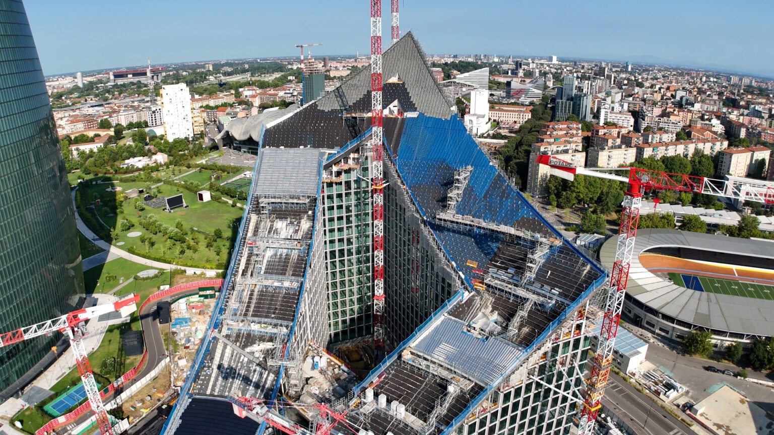
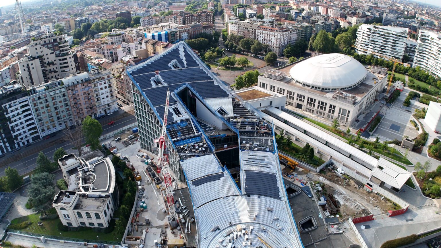
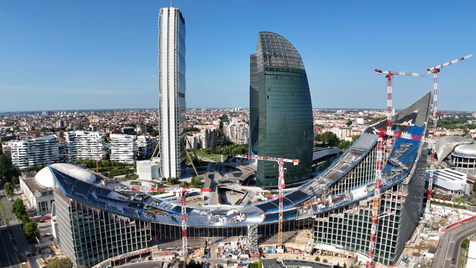
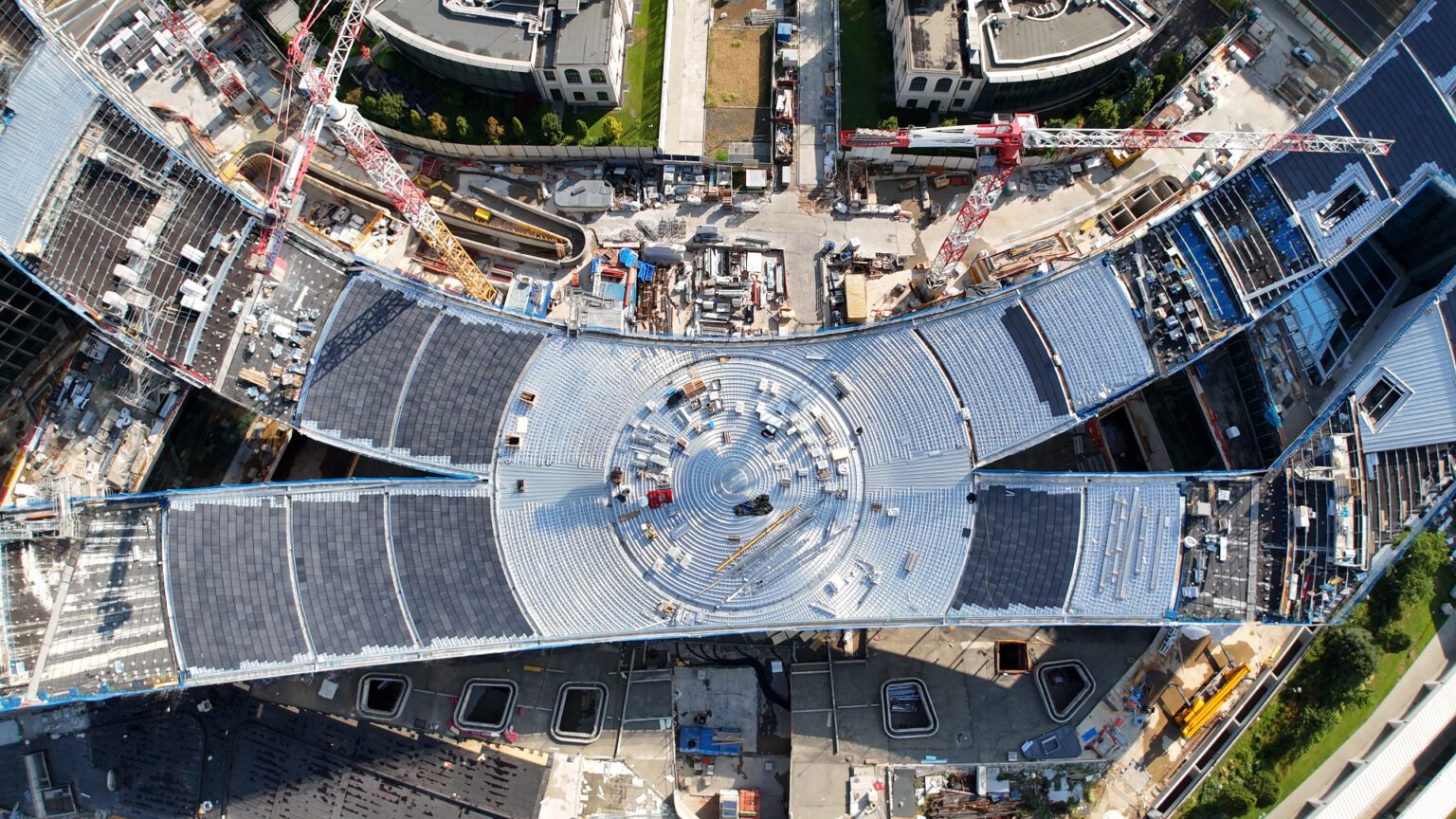
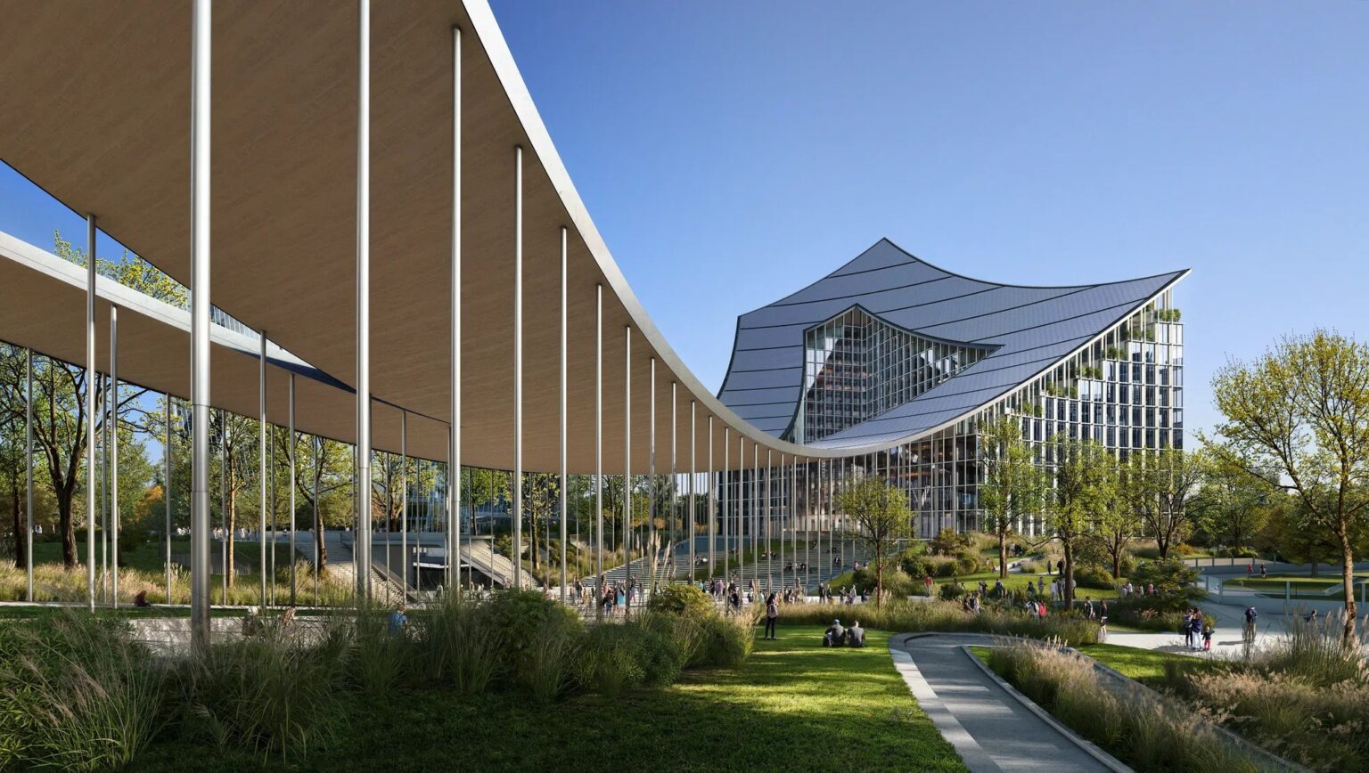
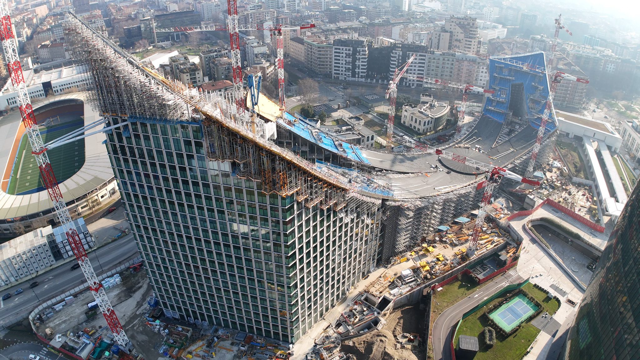
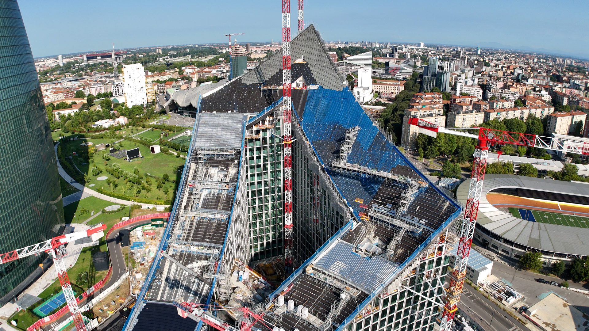
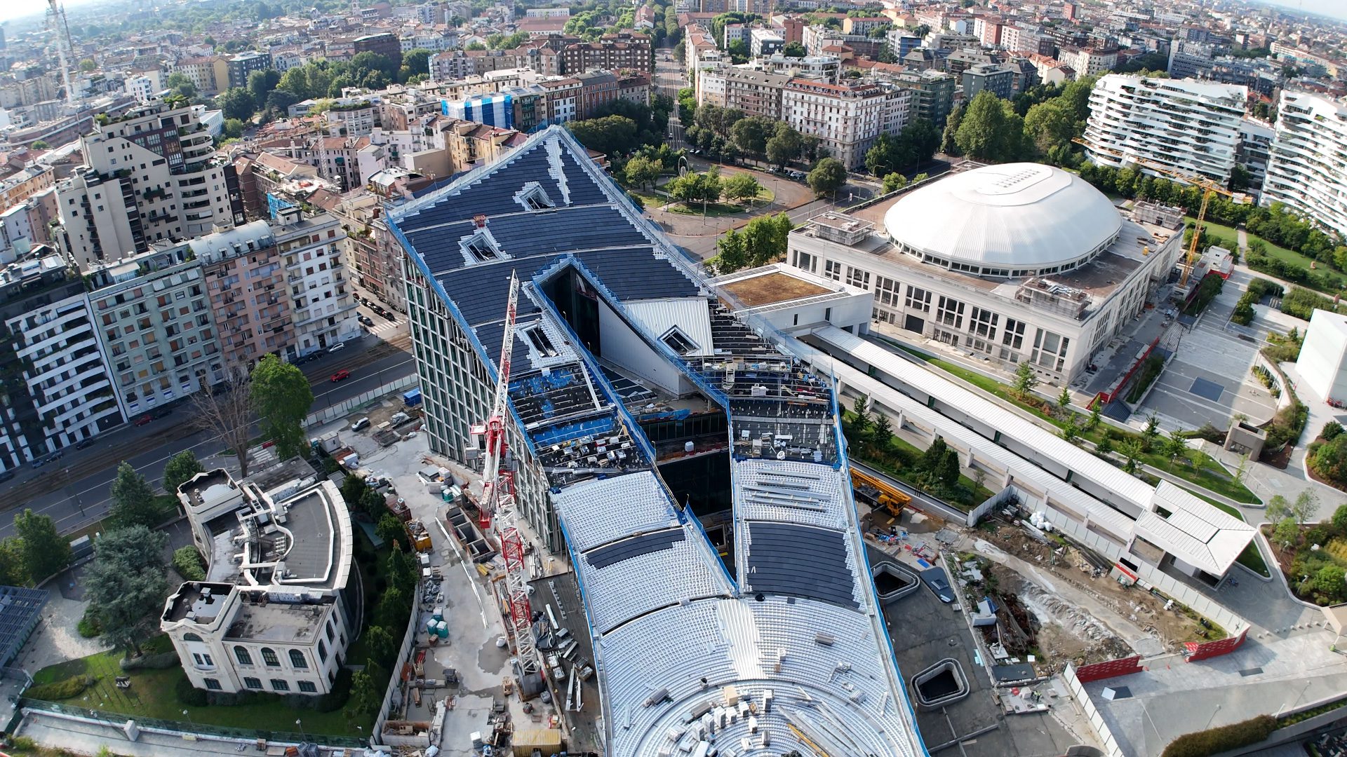
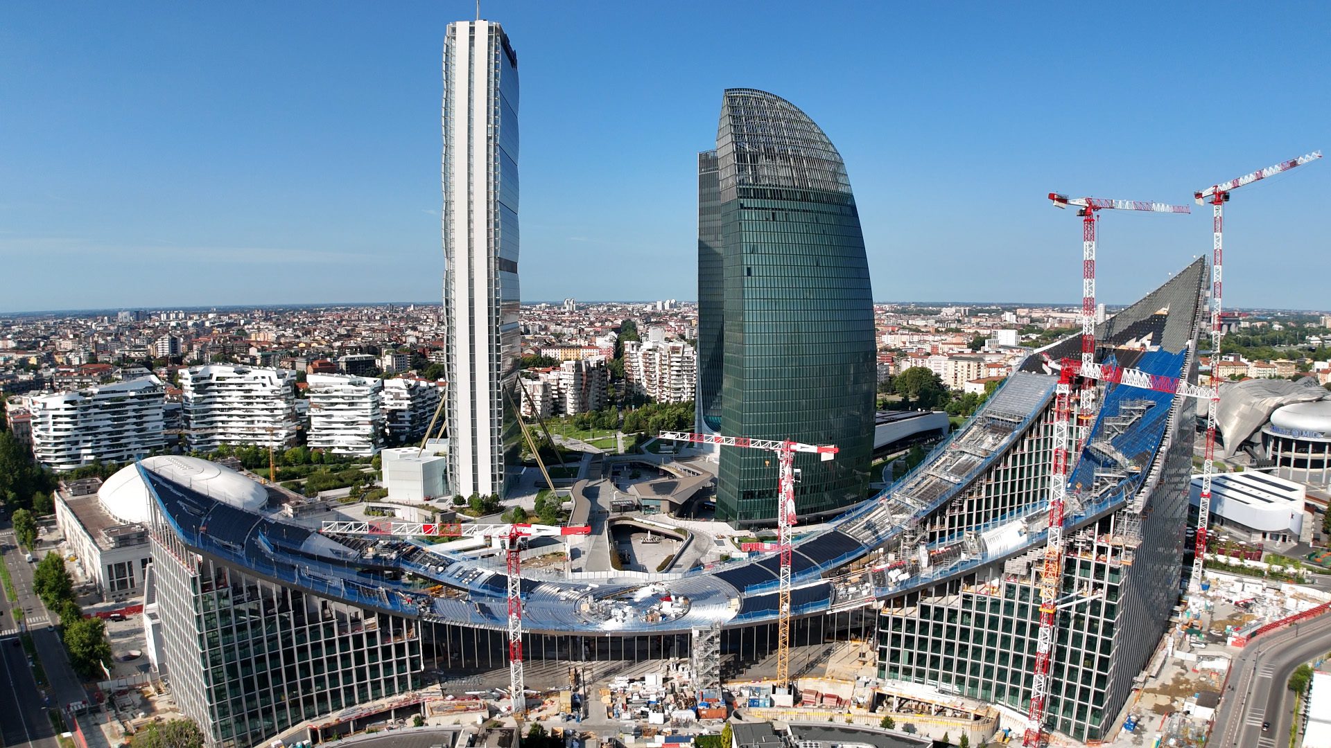
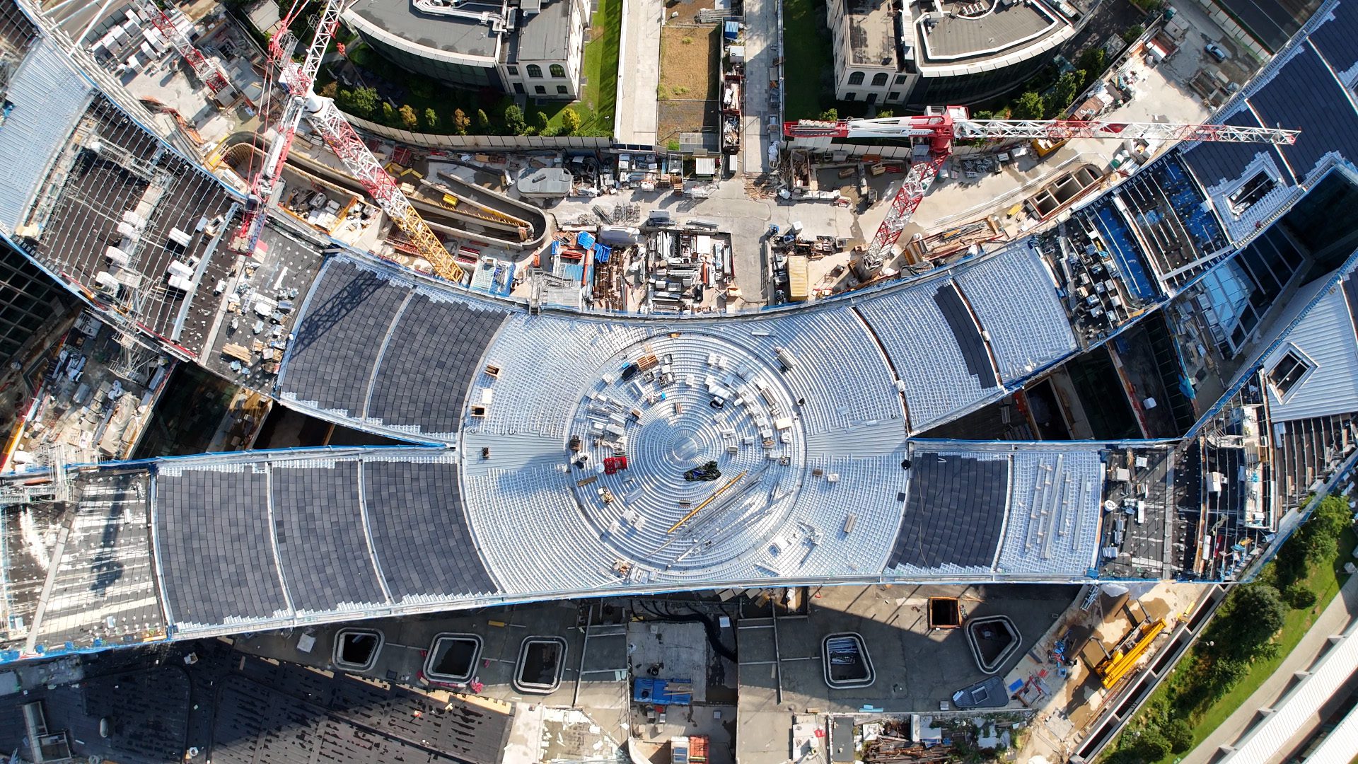
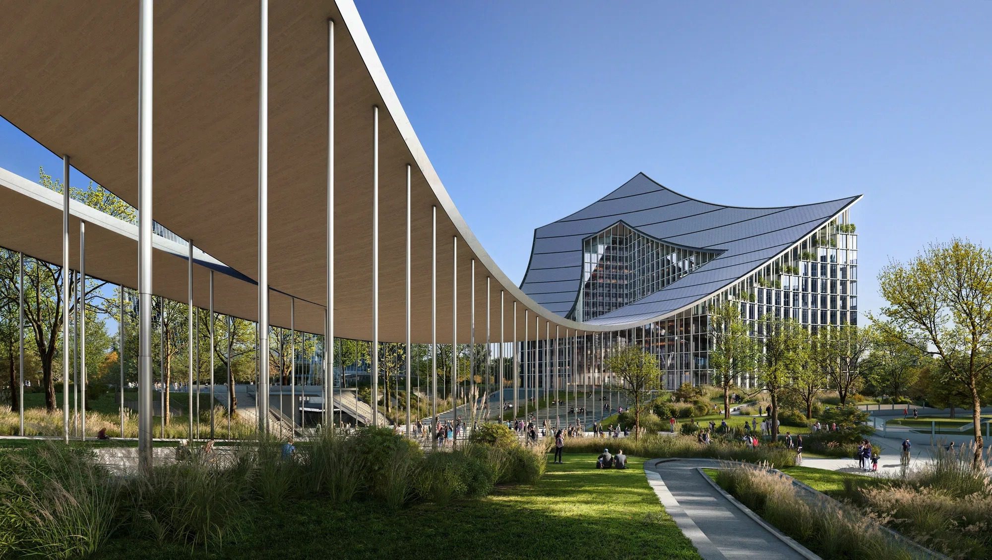
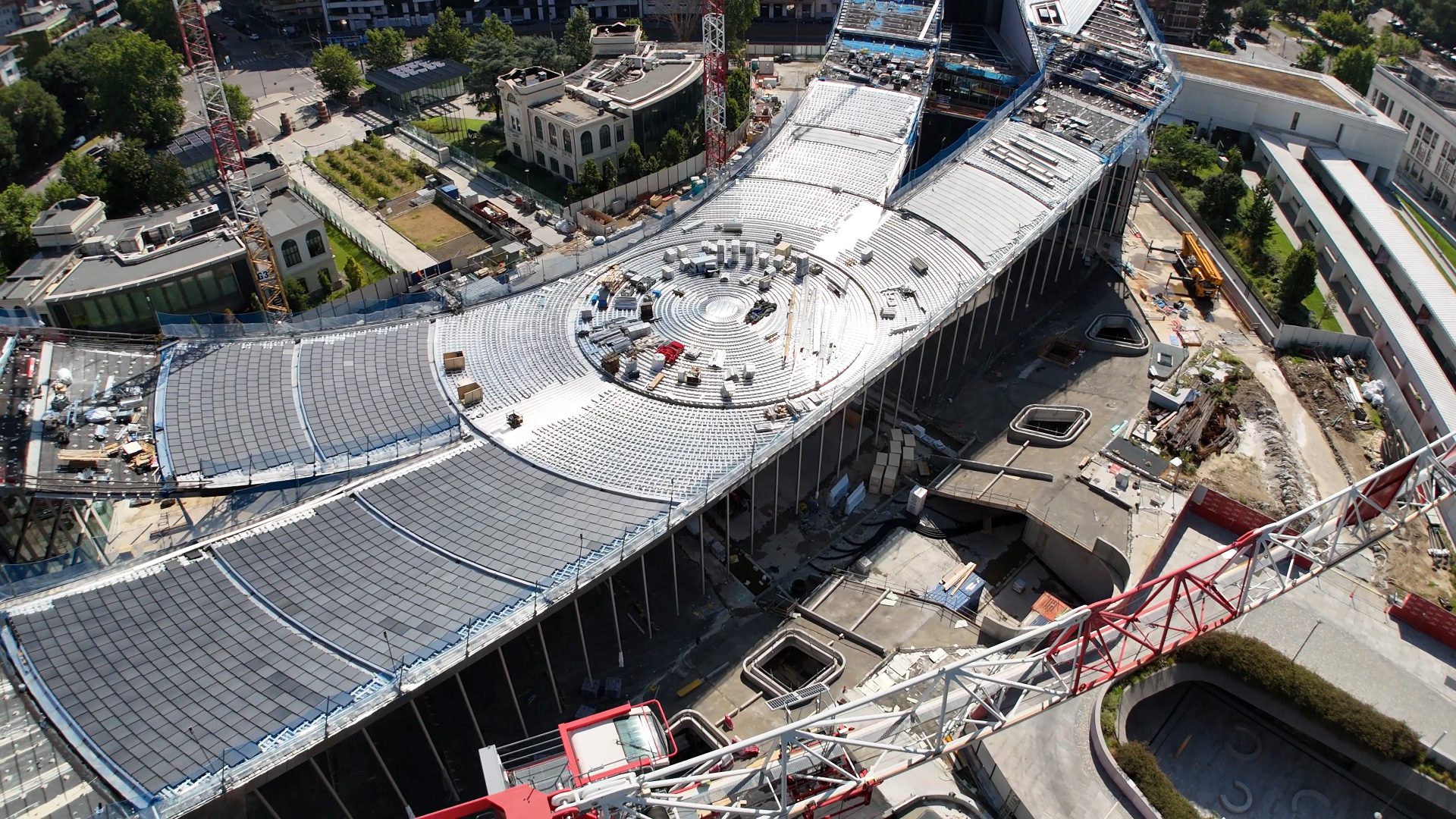
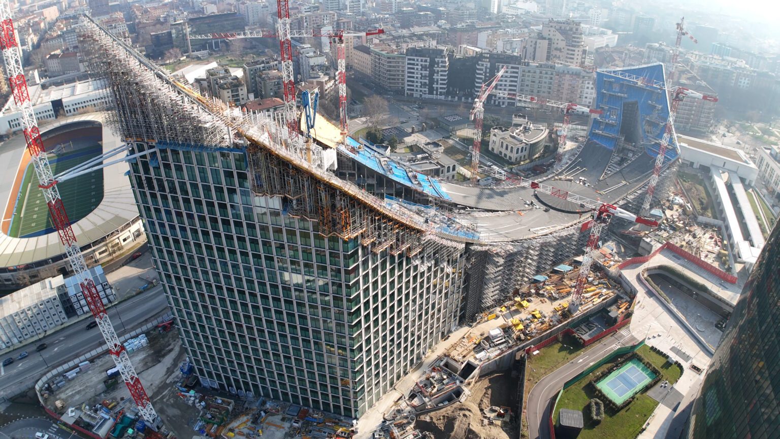
The Canopy is one of the most distinctive elements of CityWave, the project designed by BIG – Bjarke Ingels Group that completes Milan’s CityLife district. The central timber Canopy spans approximately 140 metres between the two main buildings, RD and RE, defining a covered public space through a suspended double-curved surface of approximately 4,500 m².

HB Holzner & Bertagnolli Engineering, responsible for the structural and geotechnical design of CityWave, developed the Canopy’s innovative load-bearing system and integrated it with the structures of the two buildings.

The Canopy is not an independent structural element. The actions generated by the suspended system are transferred to the roof structures of RD and RE, then through the reinforced-concrete cores and ultimately to the foundations. The project therefore required an integrated design approach, in which geometry, stiffness, strength and deformation were assessed by considering the interaction between all structural components.

A suspended roof integrated with the buildings

The structural concept of the Canopy is based on a system of cables suspended between the two buildings, without a series of intermediate vertical supports.

The forces generated by the roof are transferred to the upper structures of RD and RE and then carried through the cores to the foundations. At roof level, the horizontal force components reach values in the order of 12,000–15,000 kN.

The structural behaviour cannot be accurately represented by analysing the individual elements independently. Stiffness, deformation and boundary conditions must be assessed within a global structural model capable of reproducing the interaction between the suspended roof and the two buildings.
The load-bearing system: 19 cables and a CLT deck

The structural solution developed for the Canopy combines strand cables with structural timber. The primary suspension system consists of 19 cables made up of strands and arranged on three levels. The technology is derived from systems used in large cable-supported structures and adapted to the specific geometry and construction requirements of CityWave.

In the section between RD and RE, the cables follow a straight alignment in plan. This configuration prevents the introduction of unwanted transverse force components within the roof structure. Near the buildings, the strands are deviated towards their respective anchorage zones.

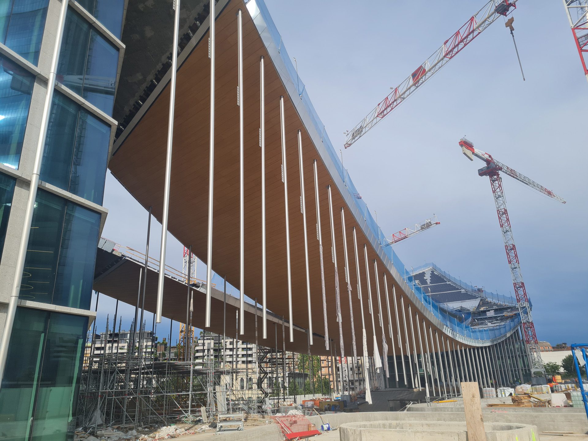
The cable system is combined with a timber deck consisting of five cross-oriented layers of CLT panels, with an overall thickness of approximately 40 centimetres and a structural timber volume of nearly 1,800 m³. The panels perform several functions simultaneously: they distribute loads to the cables, increase both the flexural and in-plane stiffness of the roof, and enable the construction of the double-curved surface defined by the architectural design.

The structural response of the Canopy therefore results from the combined action of the two systems. The cables provide the efficiency of the suspended load-bearing mechanism, while the CLT build-up contributes to stiffness, load distribution and the geometric definition of the surface.

Load transfer to RD and RE

One of the key aspects of the design concerns the connection between the Canopy cables and the reinforced-concrete structures of the two buildings. The high concentrated forces transmitted by the cable system require specifically designed roof structures capable of collecting these actions and distributing them to the vertical cores.

The roofs of RD and RE consist of large cast-in-place reinforced-concrete slabs characterised by complex geometries and substantial thicknesses. Post-tensioning systems are integrated within them to control stresses and deformations.

The horizontal actions are then transferred to the reinforced-concrete cores, which must resist not only vertical loads, wind actions and seismic forces, but also the permanent horizontal components generated by the Canopy.

Vertical post-tensioning was introduced in the cores most heavily involved in transferring these forces. The prestressing action helps reduce tensile stresses, cracking and long-term deformation effects.


Geometry and construction sequence

For a suspended structure of this scale, the construction sequence forms an integral part of the structural design. The geometry of the Canopy is initially established using temporary works and surveying systems. The timber panels and the different cable levels are then installed progressively until the complete structural build-up is formed.

The subsequent stressing of the strands changes both the stress state of the roof and its deformed configuration. Cable tensioning is therefore not merely a final construction operation, but a structural stage that must be carried out according to a predefined sequence.

Each step alters the response of the system and must progressively bring the structure towards the geometry and stress state defined by the analytical model. Controlling deformations during erection is therefore as important as verifying the final structural configuration.

The design also included robustness assessments for accidental scenarios, analysing conditions involving the potential loss of effectiveness of individual components and verifying the ability of the system to maintain a controlled structural response.

Integrated modelling and BIM coordination

The high degree of interaction between the Canopy and the buildings required advanced structural modelling and continuous coordination between geometry, analysis and detailed design. The global model must simultaneously represent the behaviour of the cables, timber components, post-tensioned structures, reinforced-concrete cores and foundations. In addition, the different structural configurations occurring throughout the construction process must also be taken into account.

BIM-based design and coordination made it possible to integrate three-dimensional geometries, post-tensioning systems, connections and interfaces, while keeping the architectural definition of the surface aligned with the requirements arising from structural behaviour.

Wind and dynamic response

The geometry and low self-weight of the Canopy required a specific investigation of its behaviour under wind loading. A large, suspended surface with relatively low stiffness may be susceptible to dynamic phenomena that require more advanced assessment than the procedures typically adopted for conventional structures.

Its aeroelastic behaviour was therefore investigated through dedicated wind-tunnel testing. The tests made it possible to determine the pressure distribution across the surface and assess the dynamic response of the roof within the urban context of CityLife. Wind-tunnel tests were carried out in Canada and at Politecnico di Milano using 1:70 scale models.

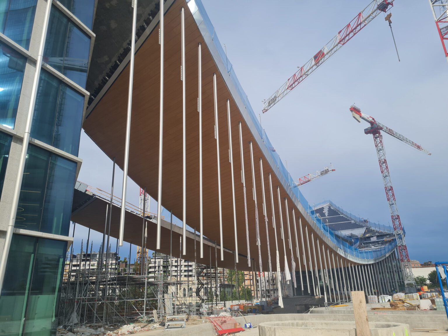
The experimental results contributed to the development of the oscillation-control system. Vertical elements known as fins are positioned along the perimeter of the Canopy. Some are used for rainwater drainage, while others house specifically designed damping devices internally at their bases, intended to reduce wind-induced oscillations. These are ECDs – Eddy Current Dampers.

The fins therefore do not provide vertical support to the roof. The primary load-bearing mechanism remains the suspended cable system, while the damping devices installed at the base of selected fins act on the dynamic response of the structure.

Experimental testing and structural monitoring

The CLT build-up was also subjected to dedicated experimental testing campaigns carried out at the University of Trento. The tests investigated connection behaviour, stiffness, strength and the dynamic response of the timber structure, allowing experimental data to be compared with the assumptions adopted in the numerical models.

Structural performance will continue to be monitored throughout the service life of the building through a permanent structural monitoring system. Accelerometers, inclinometers, displacement sensors and other instruments will record the static and dynamic response of the Canopy over time, making it possible to compare the actual behaviour of the structure with the response predicted during the design phase.

The CityWave Canopy is therefore a case in which the design of the central roof over the public square cannot be separated from that of the buildings supporting it. Strand cables, CLT, reinforced-concrete structures and post-tensioning systems work together as a single load-bearing system, whose final configuration depends not only on the sizing of individual components but also on the control of deformations and construction stages.

HB’s contribution operates precisely at this scale: from the definition of the structural concept to global modelling, from load transfer and erection sequences to experimental verification and long-term structural monitoring.